Wireless M-Bus to NB-IoT - Configuration Messages
Guide to the communication protocol of the wireless M-Bus to NB-IoT converters ACR-CV-1xxNI-W-D2 and ACR-CV-1xxNI-W433-D2.
Introduction
This manual describes a use of the following Lua script Lua script which sets up a protocol to communicate with the ACRIOS NI-W-D converter and a server configured for this purpose. The system makes use of various payload messages (uplink and downlink) that enable both data gathering and device configuration.
First, we look at general principles used in this communication protocol, then there is an overview of uplink messages (device → server communication), then there is an overview of downlink messages (server → device communication) and finally there is a full example of communication between an ACR-CV unit and the server along with an explanation.
Payload
The communication between the device and the server is achieved with help of payload messages. The payload messages are sent in two directions.
- Uplink Message
- This message type is sent from the converter to the server with the requested information.
- Downlink Message
- This message type is sent from the server to the converter with specific commands.
Uplink Command Bytes
| Command Byte | Description |
|---|---|
| 0xFF | Gather report (Legacy) |
| 0xFE | Configuration acknowledge |
| 0xFD | wM-Bus IDs acknowledge |
| 0xFB | Scanning done |
| 0xFA | Status report |
| 0xF9 | Bootloader request |
| 0xF7 | Bootloader answer |
| 0xF6 | wM-Bus IDs checksum |
| 0xF4 | Gather report acked |
| 0xF3 | Scanned unit with mode report |
| 0xF2 | Status report extended |
| 0xF1 | Error report |
| 0xF0 0xFF | Beacon report |
| 0xF0 0xFE | Send once data |
| 0xF0 0xFD | Send once end of gathering |
| 0xF0 0xFC | Sontex ID acknowledge |
| 0xF0 0xFB | Send Sontex frame |
| 0xF0 0xFA | Send number of Sontex IDs |
| 0xF0 0xF9 | Sontex scan finished |
| 0xF0 0xF8 | Scan report with payload |
| 0xF0 0xF7 | BUP key readout |
| 0xF0 0x00 | Data report with ACRCOM |
Downlink Command Bytes
| Command Byte | Description |
|---|---|
| 0x01 | Send IDs |
| 0x02 | Send config |
| 0x03 | Request config |
| 0x04 | Request scan |
| 0x05 | Request IDs |
| 0x06 | Request status |
| 0x07 | Request reset |
| 0x08 | Downlink send ack |
| 0x09 | Specified Error Report |
| 0x0A | Error Report |
| 0x0B | Planned gathering |
| 0x0C | Set Sontex list of IDs |
| 0x0D | Request Sontex ID checksum |
| 0x0E | Request Sontex scan |
| 0x0F | Request scan with payload |
| 0x10 | Set Sensus BUP key |
| 0x11 | Get Sensus BUP key |
Communication Diagrams
This section outlines communication essential for various configurations such as ID readout, encryption keys in BUP mode, and other processes described further below. Every process is clearly depicted and explained through UML diagrams.
Configuration
The primary purpose of downlink communication is remote configuration of the target device. Configuration messages are sent in response to specific messages received from the uplink device. Keep in mind that not all the messages qualify for a response. Downlink messages are only processed when they respond to the following uplink messages:
- 0xF4
- 0xF0 0xFF
- 0xF0 0xFA
- 0xF0 0xF9
- 0xFB
- 0xF1 (specifically when triggered by command 0x0A)
- 0xF0 0xFD
General Configuration
This diagram explains a configuration procedure following a beacon message.
If the device is not configured, it sends a 0xF4 0x01 gather report message. Without a filter of IDs set, the converter will automatically send an uplink every hour to open a receive window for a possible downlink.
Setting IDs
- Wireless M-Bus devices
Below is a diagram showing a process of Wireless M-Bus ID configuration.
- Sontex devices
Configuring Sontex devices involves scanning configured IDs, unlike with the usual Wireless M-Bus devices. This difference is caused by the need of these meters to receive a request for a specified meter ID , in other words, there is a need for active communication, rather than gathering frames passively sent by the meters (passive communication). The benefit of the extra scan in the configuration procedure is that the meter's availability is ensured.
Setting BUP Keys
This section covers the procedures for setting and retrieving BUP (Bubble Up Protocol) keys. Further explanation can be found in the diagrams below.
BUP is a communication protocol used by Sensus/Xylem water meters (MeiStream, iPerl). The communication is encrypted, and if the decryption key is provided, the ACR-CV device can verify the integrity of received frames. Without the decryption key, the ACR-CV cannot verify the integrity and checksum of received BUP messages. Therefore, the key is required.
Note that if an empty key is set, the default BUP Sensus key is used.
Set BUP Key
The following diagram showcases how the process of setting the BUP key works.
Get BUP Key
The following diagram showcases how the process of getting the BUP key works.
Gathering Modes
In addition to specific communication configurations, the Lua scripts available for this device allow for three different approaches to scheduled gathering:
- Multimode: This mode is managed by the server, this mode operates using the following Lua script. Once a configuration message is received from the server, the device enters scheduled gathering mode. It regularly sends beacon messages to maintain communication with the server. In response, the server calculates the necessary interval until the next gathering session and sends a scheduled gathering message back to the device, which then waits until the next gathering session.
Pros
- You can set-up an exact list od IDs with help of Wireless M-Bus ID filter.
- This way, the readout cycle can terminate sooner and does not send any unwanted meter data.
Cons
- It is required to send the configuration from the server.
-
SendOnce: This mode is manually configured directly in the following Lua script. This script works similarly to "Multimode" but does not require server for configuration:
workdayOnly = true -- true for workdays only, false for all days
numberOfDays = 3 -- the number of days/workdays since the end of month
startHour = 10 -- an hour of the start of the readout
randomizeSeconds = 7200 -- up to 7200s~2hrs of delayed start since startHour
Pros
- The Lua script contains the configuration itself, therefore there is no need for configuration from the server.
- The device sends data from every meter in its range.
Cons
- There is no option to configure Wireless M-Bus ID filter.
- The readout cycle may take longer, because it scans for data from meter for an exactly specified amount of time.
-
Periodic Wake-Up: This mode is used by default when no specific gathering schedule is configured. Both of the Lua scripts use a predefined interval to wake up periodically:
pDaysDef = 7 -- days
pHrsDef = 0 -- hours
pMinsDef = 0 -- minutes
In the meantime, the device sends beacon messages to maintain connectivity.
You can look at the following diagram for a simple representation of how the gathering modes differ.
Scheduled Gathering
The diagram below showcases how the device regularly sends beacon messages to maintain communication with the server. In response, the server calculates the necessary interval until the next gathering session and sends a "Planned gathering" message back to the device, which then waits until the next gathering session.
Passive Gathering
Passive gathering is often used by:
- standard Wireless M-Bus devices
- Apator Metra
- Sensus
- BUP and others
Active Gathering
Sontex devices, which are using protocol Radian, are among devices that use active gathering. This protocol requires query-response type of communication and for that reason it is called "Active".
In Active gathering, the 0xF4 report is sent with an empty list of IDs.
Combination of Both Active and Passive Gathering
Both Active and Passive types of gathering are combined in this case. The difference is that the device maintains two separate lists of IDs for Passive and Active gathering, and the devices using Passive gathering are processed first, while devices using the Active gathering are processed last. For further details, see the diagram below.
Scanning for Devices
There are two approaches to scanning: Passive and Active. Passive Wireless M-Bus devices send data frames periodically, whereas Active devices, such as Sontex, require a request before they transmit data. The diagrams below showcase the communication between the server and the device.
-
Wireless M-Bus devices
The unit scans for nearby wM-Bus IDs and sends its device ID, RSSI, and manufacturer ID to the server/backend. This feature is used for automatic allocation based on RSSI or general ID sniffing.
-
Sontex devices
Sontex devices require a request for a specific ID to receive a response; therefore, the list of IDs must be sent in combination with the scan command. See the section here and diagram below.
Uplink Command Bytes
This section provides description for uplink messages that are the individual payloads sent by the converter to the server.
Data Report
This is a periodic report sent by the converter, where the first byte defines the local Wireless M-Bus ID followed by raw data from the Wireless M-Bus device.
Each device is limited to 240 local Wireless M-Bus IDs in range from 0 (0x00) to 127 (0xF0)
| Example | Description | Size | Byte Number |
|---|---|---|---|
| 0x01 | Local wM-Bus ID | [1B] | 1 |
| 0xXX | Raw device data | [xB] | 2 |
Gather Report (0xFF) (Legacy)
This command gathers report for number of devices (N). The report is sent after every scanning cycle and includes information about which ID was found and which was not.
Note that this command is marked as Legacy. It is used only in the older versions of the Lua script.
Payload Description
| Example | Description | Size | Byte Number |
|---|---|---|---|
| 0xFF | Command byte | [1B] | 1 |
| 0x01 | ID1 was found | [1B] | 2 |
| 0x01 | ID2 was found | [1B] | 3 |
| 0x00 | ID3 was not found | [1B] | 4 |
| 0x01 | ID4 was found | [1B] | 5 |
| 0xXX | xxxxxx | [NxB] | 6 |
0x01 = IDs received
0x00 = IDs not found
Configuration Acknowledgment (0xFE)�
This message confirms that the configuration was successfull.
Payload Description
| Example | Description | Size | Byte Number |
|---|---|---|---|
| 0xFE | Command byte | [1B] | 1 |
| 0x78 | Time per entry [s] | [1B] | 2 |
| 0x00 | Gather time S mode [s] | [1B] | 3 |
| 0x00 | Gather time T/C mode [s] | [1B] | 4 |
| 0x00 | Wake up period [Days] | [1B] | 5 |
| 0x00 | Wake up period [Hours] | [1B] | 6 |
| 0x0F | Wake up period [minutes] | [1B] | 7 |
| 0x06 | Filter length | [1B] | 8 |
| 0x0E | Config version | [1B] | 9 |
| 0x1E | Gather time M mode [s] | [1B] | 10 |
Time per entry - This is a time in seconds for how long it took to scan for one ID. The total scan time is calculated by multiplying the time by the amount of IDs.
Gather time S, T, and M mode - This is a time in seconds defining for how long the device should receive the data in S, T, or M mode.
Filter length - This is the total number of device IDs stored in the memory of a device.
Config version - This is a number that increments with each new configuration (0 to 255).
W M-Bus IDs Acknowledgment (0xFD)
This message confirms configuration of the wM-Bus IDs.
Payload Description
| Example | Description | Size | Byte Number |
|---|---|---|---|
| 0xFD | Command byte | [1B] | 1 |
| 0x03 | Filter length [= N] | [1B] | 2 |
| 0x90 0x82 0xCB 0x01 | Filter ID 1 | [4B] | 3-6 |
| 0x74 0x82 0xCB 0x01 | Filter ID 2 | [4B] | 7-10 |
| 0x75 0x82 0xCB 0x01 | Filter ID 3 | [4B] | 11-14 |
| 0xXX 0xXX 0xXX 0xXX | N x Filter ID X | [N x 1B] | N |
The byte order of filter IDs (as seen in the example above) starts with LSB and ends with MSB (little endian). Here are some examples of IDs:
ID1 = 01 CB 82 90
ID2 = 01 CB 82 74
ID3 = 01 CB 82 75
Scanning Done (0xFB)
This report is sent after the scanning cycle is completed.
| Example | Description | Size | Byte Number |
|---|---|---|---|
| 0xFB | Command byte | [1B] | 1 |
Status Report (0xFA)
Status report contains signal strength, battery voltage and Lua script version that the device is currently using.
Payload Description
| Example | Description | Size | Byte Number |
|---|---|---|---|
| 0xFA | Command byte | [1B] | 1 |
| 0x0F 0x0B 0x0E | Status report | [3B] | 2-4 |
| 0x33 0x2E 0x30 | Script version | [3B] | 5-7 |
The status report contains 3 bytes. where:
- 1st byte (0x0F) is a signal strength.
- 2nd byte (0x0B) is the LSB of battery voltage.
- 3rd byte (0x0E) is the MSB of battery voltage.
Bootloader Request (0xF9)
Note that the following example is split into multiple parts for better understanding, but otherwise it is sent in a form of a single frame.
Below is the first part of the frame, it contains bootloader specific command byte, bootloader version and bootloader request type.
These are the different bootloader request types:
- BL_REQ_ALL - Contains the entire frame, including all three following parts:
- NB-IoT
- Chip IDs
- CRC section
- BL_REQ_NBIOT_IDS - contains only NB-IoT related part.
- IMEI, IMSI, ICCID separated with 0x00 (can be be seen in the example below).
- BL_REQ_CHIP_IDS - contains only chip information.
- BL_REQ_SECTIONS_CRC - contains only CRC part of the frame.
| Example | Description | Size | Byte Number |
|---|---|---|---|
| 0xF9 | Command byte | [1B] | 1 |
| 0x06 0x06 | Version | [2B] | 2-3 |
| 0x00 | BL request type | [1B] | 4 |
NB-IoT IDs Section (BL_REQ_NBIOT_IDS)
Payload Description
IMEI
| Example | Description | Size | Byte Number |
|---|---|---|---|
| 0x38 0x36 0x38 0x33 0x33 0x33 0x30 0x33 0x35 0x30 0x33 0x37 0x31 0x32 0x32 | IMEI (868333035037122) | xB (ASCII) | 1-15 |
| 0x00 | Split by zero | [1B] | 16 |
IMSI
| Example | Description | Size | Byte Number |
|---|---|---|---|
| 0x39 0x30 0x31 0x34 0x30 0x35 0x37 0x31 0x30 0x30 0x35 0x38 0x39 0x31 0x35 | IMSI (901405710058915) | xB (ASCII) | 1-15 |
| 0x00 | Split by zero | [1B] | 16 |
ICCID
| Example | Description | Size | Byte Number |
|---|---|---|---|
| 0x38 0x39 0x38 0x38 0x32 0x32 0x38 0x30 0x30 0x30 0x30 0x30 0x31 0x30 0x30 0x39 0x35 0x34 0x35 0x39 | ICCID (89882280000010095459) | xB (ASCII) | 1-20 |
| 0x00 | Split by zero | [1B] | 21 |
Chip IDs Section (BL_REQ_CHIP_IDS)
Payload Description
Chip EUI
| Example | Description | Size | Byte Number |
|---|---|---|---|
| 0x5D 0x00 0x31 0x00 0x0D 0x50 0x42 0x59 0x37 0x39 0x38 0x20 | Chip EUI (0x203839375942500D0031005D) | 12B (little endian) | 1-12 |
Flash size in kB, Chip package, Chip ID & Rev
| Example | Description | Size | Byte Number |
|---|---|---|---|
| 0x00 0x01 0x00 0x00 | Flash size in kB (100 kB) | 4B (little endian) | 1-4 |
| 0x0A 0x00 0x00 0x00 | Chip package (10) | 4B (little endian) | 5-8 |
| 0x35 0x64 0x01 0x10 | Chip ID & Rev (REV Z, id 435) | 4B (little endian) | 9-12 |
Chip Package Types:
These numbers refer to commonly used chip package types.
- 0 - LQFP64
- 10 - UFQFPN48
- 11 - LQFP48
Revision:
These following bytes allow identification of commonly used revisions.
0x10016435 → 0x1001
((0x10016435 & 0xFFFF0000) >> 16)
- 0x1000 - REV A
- 0x1001 - REV Z
- 0x2001 - REV Y
Chip ID:
These following bytes refer to commonly used chip IDs.
0x10016435 → 0x435
0x10016435 & 0xFFF
- 0x435 = STM32L43xxx/STM32L44xxx
- 0x462 = STM32L45xxx/STM32L46xxx
- 0x464 = STM32L41xxx/STM32L42xxx
CRC Section (BL_REQ_SECTIONS_CRC)
Payload Description
| Example | Description | Size | Byte Number |
|---|---|---|---|
| 0xF5 0x09 | CRC16 BL | 2B (little endian) | 1-2 |
| 0x5B 0x1B | CRC16 Config | 2B (little endian) | 3-4 |
| 0x56 0x38 | CRC16 App | 2B (little endian) | 5-6 |
| 0x94 0x56 | CRC16 Lua | 2B (little endian) | 7-8 |
| 0x80 0x9E | CRC16 Fragment | 2B (little endian) | 9-10 |
Bootloader Answer (0xF7)
This responds to a command given by a downlink sent from the server.
Payload Description
| Example | Description | Size | Byte Number |
|---|---|---|---|
| 0xF7 | Command byte | [1B] | 1 |
| 0x44 | Bootloader command byte | [1B] (ASCII) | 2 |
| 0xXX | Data | [xB] | x |
Bootloader Command Byte This command byte specifies the following data part, it can contain command bytes regarding writing/erasing pages and more.
Commands
Write Chunk To Scratchpad (W)
This command is used during a firmware update.
| Example | Description | Size |
|---|---|---|
| 0x57 | Write Chunk To Scratchpad | 1B |
| 0x00 0x00 0x00 0x00 0x00 | Address | 4B |
| 0x00 0x04 | Chunk Length Bytes | 2B |
| 0x6C | Chunk CRC8 | 1B |
Read Device EUI (M)
| Example | Description | Size |
|---|---|---|
| 0x4D | Command Identifier | 1B |
| 0x5D 0x00 0x31 0x00 0x0D 0x50 0x42 0x59 0x37 0x39 0x38 0x20 | Device EUI | 8B |
Read IMEI (N)
| Example | Description | Size |
|---|---|---|
| 0x4E | Command Identifier | 1B |
| 0x38 0x36 0x38 0x33 0x33 0x33 0x30 0x33 0x35 0x30 0x33 0x37 0x31 0x32 0x32 0x00 | IMEI = 868333035037122 | 16B (ASCII) |
Clear Bootloader Timeout (L)
This procedure resets internal timout.
| Example | Description | Size |
|---|---|---|
| 0x4C | Command Identifier | 1B |
AT Commands Sequencer (A)
This allows executing of AT commands in the bootloader.
| Example | Description | Size |
|---|---|---|
| 0x41 | Command Identifier | 1B |
| 0xXX | AT Answer (ASCII) | xB |
Get Pages CRC16 (C)
This calculates CRC16 of all pages (bootloader and application).
| Example | Description | Size |
|---|---|---|
| 0x43 | Command Identifier | 1B |
| 0xXXXX | Pages CRC16 | xB (2B per entry) |
Firmware Pages Write Test (T)
This tests functionality of the pages.
| Example | Description | Size |
|---|---|---|
| 0x54 | Command Identifier | 1B |
| 0xXX | Firmware Page Test Result | xB |
Read IMSI (S)
This reads an IMSI (International Mobile Subscriber Identity).
| Example | Description | Size |
|---|---|---|
| 0x53 | Command Identifier | 1B |
| 0x39 0x30 0x31 0x34 0x30 0x35 0x37 0x31 0x30 0x30 0x35 0x38 0x39 0x31 0x35 | IMSI (901405710058915) | xB (ASCII) |
Read Chunk From Scratchpad (R)
This command is used during a firmware update.
| Example | Description | Size |
|---|---|---|
| 0x52 | Command Identifier | 1B |
| 0x00 0x00 0x00 0x00 | Address | 4B |
| 0x00 0x04 | Chunk Length | 2B |
| 0xXX | Chunk Data | xB |
Read Chip IDs (G)
| Example | Description | Size |
|---|---|---|
| 0x47 | Command Identifier | 1B |
| 0x5D 0x00 0x31 0x00 0x0D 0x50 0x42 0x59 0x37 0x39 0x38 0x20 | Chip EUI (0x203839375942500D0031005D) | 12B (little endian) |
| 0x00 0x01 0x00 0x00 | Flash size in kB (100 kB) | 4B (little endian) |
| 0x0A 0x00 0x00 0x00 | Chip package (10) | 4B (little endian) |
| 0x35 0x64 0x01 0x10 | Chip ID & Rev (REV Z, id 435) | 4B (little endian) |
Chip package types:
These numbers refer to commonly used chip package types.
- 0 - LQFP64
- 10 - UFQFPN48
- 11 - LQFP48
Revision:
These following bytes allow identification of commonly used revisions.
0x10016435 → 0x1001
((0x10016435 & 0xFFFF0000) >> 16)
- 0x1000 - REV A
- 0x1001 - REV Z
- 0x2001 - REV Y
Chip ID:
These following bytes refer to commonly used chip IDs.
0x10016435 → 0x435
0x10016435 & 0xFFF
- 0x435 = STM32L43xxx/STM32L44xxx
- 0x462 = STM32L45xxx/STM32L46xxx
- 0x464 = STM32L41xxx/STM32L42xxx
Try To Boot (K)
This command skips bootloader into application.
| Example | Description | Size |
|---|---|---|
| 0x4B | Command Identifier | 1B |
Erase Page At Address (D)
| Example | Description | Size |
|---|---|---|
| 0x44 | Command Identifier | 1B |
| 0x00 0x00 0x00 0x00 | Address | 4B |
Uncompress And Flash From Scratchpad (X, E, I, Y, U)
This command is used during a firmware update.
Note that you have to replace "X" with the specific command identifier (E, I, Y, U) for the respective commands.
| Example | Description | Size |
|---|---|---|
| 0x58 / 0x45 / 0x49 / 0x59 / 0x55 | Command Identifier | 1B |
| 0x00 0x00 0x00 0x00 | Flash Address | 4B |
| 0xXX | After Decompression CRC8 | 1B |
| 0xXX | Flashing Error Code | 1B |
| 0xXX | Flash Driver Error Flags | 4B |
Flash From QSPI (Q)
This executes an update from QSPI.
| Example | Description | Size |
|---|---|---|
| 0x51 | Command Identifier | 1B |
W M-Bus IDs Checksum (0xF6)
This message confirms the integrity of the transmission.
Payload Description
| Example | Description | Size | Byte Number |
|---|---|---|---|
| 0xF6 | Command byte | [1B] | 1 |
| 0x03 | Filter length [= N] | [1B] | 2 |
| 0x91 0x82 0xCB 0x01 | Checksum | [4B] | 3-6 |
The checksum is calculated with bitwise XOR:
RES1 = 0 ⊕ (ID1) => 0 ⊕ 0x01CB8290 = 0x01CB8290
RES2 = (RES1) ⊕ (ID2) => 0x01CB8290 ⊕ 0x01CB8274 = 0xE4
RES3 = (RES2) ⊕ (ID3) => 0xE4 ⊕ 0x01CB8275 = 0x01CB8291
…
RESN = (RESN-1) ⊕ (IDN)
The last calculated value is the checksum.
Gather Report Acknowledged (0xF4)
Gather report is sent at the end of data gathering.
| Example | Description | Size | Byte Number |
|---|---|---|---|
| 0xF4 | Command byte | 1B | 1 |
| 0x31 | Relative counter (49) | 1B | 2 |
| 0xXX | Bit Field of Received wM-Bus IDs | 1B | 3 |
Example
Here is a showcase of how a bitfield could look like:
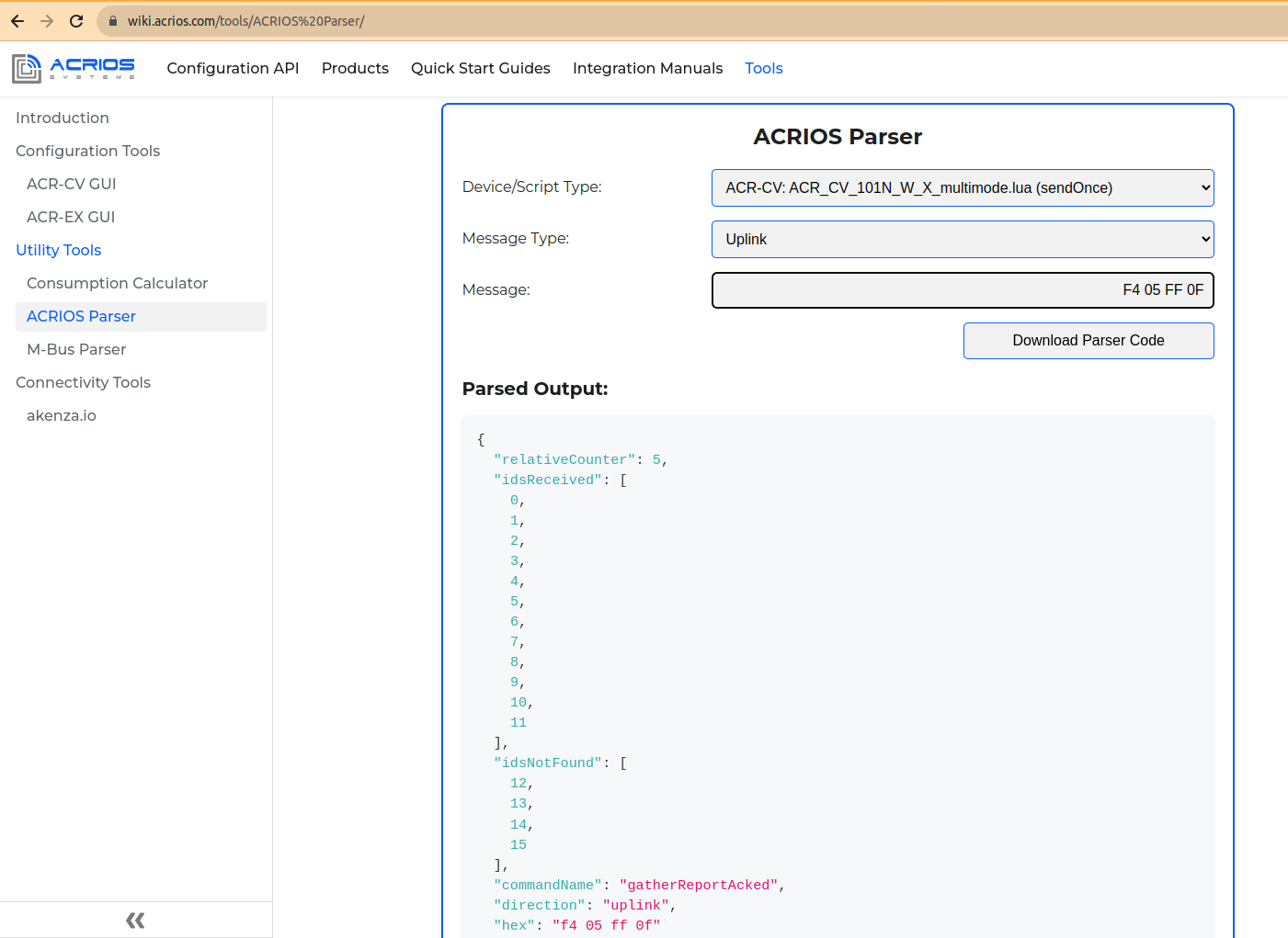
The last two bytes can be converted into report, which devices were received, and which were not.
You can test this out with the help of our parser tool - use N_W_X_multimode.lua (sendOnce).
Note that the bit field byte is present only when the filter of Wireless M-Bus IDs is configured.
Scanned Unit With Mode Report (0xF3)
This provides information about individual devices.
Payload Description
| Example | Description | Size | Byte Number |
|---|---|---|---|
| 0xF3 | Command byte | 1B | 1 |
| 0x03 | Device type ID 1 | 1B | 2 |
| 0xAB 0xC1 0xFF 0x11 | ID 1 | 4B | 3-6 |
| 0x14 0x06 | Manufacturer ID 1 | 2B | 7-8 |
| 0xBB 0xFF | RSSI ID 1 | 2B | 9-10 |
| 0x02 | Mode ID 1 | 1B | 11 |
| 0x03 | Device type ID 2 | 1B | 12 |
| 0xF7 0xC1 0xFF 0x11 | ID 2 | 4B | 13-16 |
| 0x14 0x06 | Manufacturer ID 2 | 2B | 17-18 |
| 0xA3 0xFF | RSSI ID 2 | 2B | 19-20 |
| 0x02 | Mode ID 2 | 1B | 21 |
| 0x.. | ... | xB | x |
Device type - is given by a wM-Bus device manufacturer and can tell you whether hot or cold water is used, ITN, or other device types. Please consult the OMS Metering protocol for additional details.
Manufacturer ID - is given by a wM-Bus device manufacturer.
RSSI - is Received Signal Strength Indication. A higher number indicates higher signal strength.
Modes:
- 0x00 = S Mode
- 0x01 = T/C Mode
- 0x02 = M Mode - proprietary protocol. Reach out to us for the specification and closer information.
- 0x03 = SENSUS434 - wM-Bus T-mode at 434.475 MHz, used by devices from Sensus.
- 0x04 = BUP433 - proprietary protocol (433 MHz band version) from Sensus used at Meistream, iPerl, ...
- 0x05 = BUP868 - proprietary protocol (868 MHz band version) from Sensus used at Meistream, iPerl, ...
Extended Status Report (0xF2)
Extended status report contains signal strength, battery voltage, IMEI and Lua script version that the device is currently using.
Payload Description
| Example | Description | Size | Byte Number |
|---|---|---|---|
| 0xF2 | Command byte | 1B | 1 |
| 0x32 0x2E 0x32 | Script version (1.1) | 3B (ASCII) | 2-4 |
| 0x00 | Zero terminatition | 1B | 5 |
| 0x0E | Signal [CSQ units] (14) | 1B | 6 |
| 0x30 0x0E | Battery voltage [mV] (3561 = 3.5V) | 2B (little endian) | 7-8 |
| 0x38 0x36 0x38 0x33 0x33 0x33 0x30 0x33 0x35 0x30 0x33 0x37 0x31 0x32 0x32 0x00 | IMEI = 868333035037122 | 16B (ASCII) | 9-24 |
The following example can be interpreted as:
Lua script version → 0x332E32 → 3.2
Note that the Lua script version may exceed 3 bytes in size and it is terminated by a null character.
Signal → 0x0E → 14 CSQ units
Battery voltage → 0x0E30 → 3632 mV
Error Report (0xF1)
Error report is sent after the device restarts due to an error. It uses ASCII format.
| Example | Description | Size | Byte Number |
|---|---|---|---|
| 0xF1 | Command byte | 1B | 1 |
| 0xXX | ASCII data | xB | x |
Beacon Report (0xF0 0xFF)
Beacon report provides information about device connectivity and some additional details.
Payload Description
| Example | Description | Size | Byte Number |
|---|---|---|---|
| 0xF0 0xFF | Command byte | 2B | 1-2 |
| 0x0D | Relative counter | 1B | 3 |
| 0x01 | Reason | 1B | 4 |
| 0x04 0xA9 0x00 0x00 | Uptime in [sec] | 4B (little endian) | 5-8 |
| 0x04 0xA9 0x00 0x00 | Since last TAU [sec] | 4B (little endian) | 9-12 |
| 0xA7 0x19 0x86 0x0D | Last gathering timestamp [sec] | 4B (little endian) | 13-16 |
| 0xA3 0x27 0x86 0x0D | This beacon timestamp [sec] | 4B (little endian) | 17-20 |
The following example can be interpreted as:
Uptime → 0x04A90000 → 43268 s
Since last TAU → 0x04A90000 → 43268 s
Last gathering timestamp → 0xA719860D → 226892199 + epochBase = 1678491399 => To UTC => 10/03/2023
This beacon timestamp → 0xA327860D → 226895779 + epochBase = 1678494979 => To UTC => 11/03/2023
epochBase = 1451602800-3600
The rest of the message contains data.
| Example | Description | Size | Byte Number |
|---|---|---|---|
| 0x32 0x2E 0x32 | Script version (1.1) | 3B (ASCII) | 21-23 |
| 0x00 | Zero terminatition | 1B | 24 |
| 0x0E | Signal [CSQ units] (14) | 1B | 25 |
| 0x30 0x0E | Battery voltage [mV] (3561 = 3.5V) | 2B (little endian) | 26-27 |
The following example can be interpreted as:
Lua script version → 0x332E32 → 3.2
Note that the Lua script version may exceed 3 bytes in size and it is terminated by a null character.
Signal → 0x0E → 14 CSQ units
Battery voltage → 0x0E30 → 3632 mV
| Example | Description | Size | Byte Number |
|---|---|---|---|
| 0x38 0x36 0x38 0x33 0x33 0x33 0x30 0x33 0x35 0x30 0x33 0x37 0x31 0x32 0x32 0x00 | IMEI = 868333035037122 | 16B (ASCII) | 1-16 |
| Example | Description | Size | Byte Number |
|---|---|---|---|
| 0x00 | Time Until Battery at 3250 mV [s] | 1B | 1 |
| 0x02 0x0D 0x06 | Firmware Version = 2.13.6 | 3B | 2-4 |
| 0x05 0x04 0x00 0x00 | Absolute Awake Time [s] | 4B | 5-8 |
| 0x5F 0xA0 | NB-IoT Local Area Code | 2B | 9-10 |
| 0x21 0x30 0x10 0x00 | NB-IoT Cell ID | 4B | 11-14 |
| 0x68 0x10 0x00 0x00 | NB-IoT Tracking Area Update (TAU, T3412) | 4B | 15-18 |
| 0x3E 0x00 0x00 0x00 | NB-IoT Active Timer (T3324) | 4B | 19-22 |
| 0x00 0x00 0x00 0x00 | NB-IoT Module Last Sleep Failure Timestamp | 4B | 23-26 |
| 0x00 0x00 0x00 0x00 | NB-IoT Module Sleep Failure Event Count | 4B | 27-30 |
| 0x03 | Device Reset Reason | 1B | 31 |
| 0x00 0x00 0x00 | Reserved bytes | 3B | 32-34 |
| 0x16 | CPU Temperature | 1B | 35 |
Time Until Battery
- 0 seconds = the device did not had to wait before sending NB-IoT message.
- Higher values mean weaker battery.
Absolute Awake Time
- 0x00000405 = the device spent in total 1029 seconds awake gathering or sending data since boot.
NB-IoT Local Area Code
- LAT = 0xA05F
NB-IoT Cell ID
- Cell ID = 0x00103021
NB-IoT Tracking Area Update (TAU, T3412)
- TAU = 4200 seconds (0x00001068)
NB-IoT Active Timer (T3324)
- Active Time = 62 seconds (0x0000003E)
NB-IoT Module Last Sleep Failure Timestamp
- since 1.1. 2016
- 0 means event did not happen since boot
NB-IoT Module Sleep Failure Event Count
- 0 means event did not happen since boot
Device Reset Reason
- 0 = unknown
- 1 = OBL
- 2 = Pin
- 3 = Brown Out
- 4 = SFTRST
- 5 = independent watchdog
- 6 = window watchdog
- 7 = LPWRRST
- 8 = FWRST
Reserved bytes
- should be 0x00
CPU Temperature
- 0x16 = 22 degrees Celsius
Send Once Data (0xF0 0xFE)
This Lua script is identified by this message.
| Example | Description | Size | Byte Number |
|---|---|---|---|
| 0xF0 0xFE | Command byte | 2B | 1-2 |
| 0x.. | Raw wM-Bus data | xB | x |
Send Once End of Gathering (0xF0 0xFD)
This is a report sent at the end of gathering. Related to the script above.
| Example | Description | Size | Byte Number |
|---|---|---|---|
| 0xF0 0xFD | Command byte | 2B | 1-2 |
| 0x01 | # of meters found (1) | 1B | 3 |
| 0x0A | Relative counter (10) | 1B | 4 |
Sontex ID Acknowledge (0xF0 0xFC)
This message confirms the integrity of the transmission.
Payload Description
| Example | Description | Size | Byte Number |
|---|---|---|---|
| 0xF0 0xFC | Command byte | 2B | 1-2 |
| 0x03 | # of IDs (3) | 1B | 3 |
| 0xC5 0xED 0xAB 0x01 | Checksum | 4B | 4-7 |
The checksum is calculated with bitwise XOR:
RES1 = 0 ⊕ (ID1) => 0 ⊕ 0x01CB8290 = 0x01CB8290
RES2 = (RES1) ⊕ (ID2) => 0x01CB8290 ⊕ 0x01CB8274 = 0xE4
RES3 = (RES2) ⊕ (ID3) => 0xE4 ⊕ 0x01CB8275 = 0x01CB8291
…
RESN = (RESN-1) ⊕ (IDN)
The last calculated value is the checksum.
Send a Sontex Frame (0xF0 0xFB)
It sends raw Sontex data frame.
| Example | Description | Size | Byte Number |
|---|---|---|---|
| 0xF0 0xFB | Command byte | 2B | 1-2 |
| 0x01 | Sontex ID (1) | 1B | 3 |
| 0x.. | Raw Sontex data | xB | x |
Send a Number of Sontex IDs (0xF0 0xFA)
It sends a number of received Sontex IDs.
| Example | Description | Size | Byte Number |
|---|---|---|---|
| 0xF0 0xFA | Command byte | 2B | 1-2 |
| 0x3C | Relative counter (60) | 1B | 3 |
| 0x4E | # of IDs received (78) | 1B | 4 |
Sontex Scan Finished (0xF0 0xF9)
This confirms that the scan is finished.
| Example | Description | Size | Byte Number |
|---|---|---|---|
| 0xF0 0xF9 | Command byte | 2B | 1-2 |
Scan Report with a Payload (0xF0 0xF8)
This provides information about the unit and its payload.
Payload Description
| Example | Description | Size | Byte Number |
|---|---|---|---|
| 0xF0 0xF8 | Command byte | 2B | 1-2 |
| 0x03 | Device type ID 1 | 1B | 3 |
| 0xAB 0xC1 0xFF 0x11 | ID 1 | 4B | 4-7 |
| 0x14 0x06 | Manufacturer ID 1 | 2B | 8-9 |
| 0xBB 0xFF | RSSI ID 1 | 2B | 10-11 |
| 0x02 | Mode ID 1 | 1B | 12 |
| ACRCOM | ACRCOM HEADER | 7B | 13-19 |
| 0x.. | Payload | xB | x |
| 0x03 | N * Device type ID x | N*1B | x |
| 0xAB 0xC1 0xFF 0x11 | N * ID x | N*4B | x |
| 0x14 0x06 | N * Manufacturer ID x | N*2B | x |
| 0xBB 0xFF | N * RSSI ID x | N*2B | x |
| 0x02 | N * Mode ID x | N*1B | x |
| ACRCOM | N * ACRCOM HEADER | N*7B | x |
| 0x.. | N * Payload | N*xB | x |
N marks that the frame can contain more than one frame.
Device type - is given by a wM-Bus device manufacturer and can tell you whether it is hot or cold water, ITN, or other device types. For the description please check the OMS Metering protocol.
Manufacturer ID - is given by a wM-Bus device manufacturer.
RSSI - Received Signal Strength Indication. A higher number is better.
Modes:
- 0x00 = S Mode
- 0x01 = T/C Mode
- 0x02 = M Mode - proprietary protocol. Reach out to us for the specification and closer information.
- 0x03 = SENSUS434 - wM-Bus T-mode at 434.475 MHz, used by devices from Sensus.
- 0x04 = BUP433 - proprietary protocol (433 MHz band version) from Sensus used at Meistream, iPerl, ...
- 0x05 = BUP868 - proprietary protocol (868 MHz band version) from Sensus used at Meistream, iPerl, ...
BUP Key Readout (0xF0 0xF7)
This reads out a Bubble Up Protocol key.
| Example | Description | Size | Byte Number |
|---|---|---|---|
| 0xF0 0xF7 | Command byte | 2B | 1-2 |
| 0xXX | BUP key | xB | 3-x |
Data Report with ACRCOM (0xF0 0x00)
This is a periodic report sent by the converter but it containts ACRCOM at the beginning.
Payload Description
| Example | Description | Size | Byte Number |
|---|---|---|---|
| 0xF0 | Command byte | 1B | 1 |
| 0x00 | ACRCOM start byte | 1B | 2 |
| 0xC3 0x00 | Data size | 2B | 3-4 |
| 0x3C 0xFF | Inverted data size | 2B | 5-6 |
| 0xC4 0x78 | CRC16 CCIT | 2B | 7 |
| 0x.. | Data | xB | x |
- Data size - This information defines the size of Data section that follows ACRCOM header.
0xC3 0x00 → C3 = 195 - This means the header will be followed by 195 bytes of data.
Inverted data size - This is inverted hexadecimal value of Data size.
CRC16 CCIT - This is cyclic Redundancy Check using CCITT with initial value 0xFFFF and polynomial 0x1021.
Downlink Command Bytes
This section provides description for downlink messages that are the individual payloads sent by the server to the converter.
The server side is used for the remote configuration of the converters within installations. By using the server-side for configuration over NB-IoT you can deploy out-of-the-box converters and configure them one by one after the deployment. Feel free to reach out if you are interested in using our server-side API tool.
The downlink commands are processed only as a response to these uplink commands:
- 0xF4
- 0xF0 0xFF
- 0xF0 0xFA
- 0xF0 0xF9
- 0xFB
- 0xF1 (specifically when triggered by command 0x0A)
- 0xF0 0xFD
New Filter Configuration (0x01)
This command is used to configure Wireless M-Bus filter IDs.
Payload Description
| Example | Description | Size | Byte Number |
|---|---|---|---|
| 0x01 | Command byte | 1B | 1 |
| 0x90 0x82 0xCB 0x01 | Filter ID 1 | 4B | 2-5 |
| 0x74 0x82 0xCB 0x01 | Filter ID 2 | 4B | 6-9 |
| 0x75 0x82 0xCB 0x01 | Filter ID 3 | 4B | 10-13 |
| 0xXX 0xXX 0xXX 0xXX | Filter ID X | N x 4B | N |
The byte order of filter IDs (as seen in the example above) starts with LSB and ends with MSB (little endian). Here are some examples of IDs:
ID1 = 01 CB 82 90
ID2 = 01 CB 82 74
ID3 = 01 CB 82 75
Send a Configuration (0x02)
This command sends configuration to the device.
Payload Description
| Example | Description | Size | Byte Number |
|---|---|---|---|
| 0x02 | Command byte | 1B | 1 |
| 0x78 | Time per entry [s] | 1B | 2 |
| 0x00 | Gather time S mode [s] | 1B | 3 |
| 0x00 | Gather time T/C mode [s] | 1B | 4 |
| 0x00 | Wake up period [Days] | 1B | 5 |
| 0x00 | Wake up period [Hours] | 1B | 6 |
| 0x0F | Wake up period [minutes] | 1B | 7 |
| 0x1E | Gather time M mode [s] | 1B | 8 |
| 0x01 | Inter-frame timeout [s] | 1B | 9 |
| 0x30 | Beacon period [quarter] | 1B | 10 |
Time per entry - This is a time in seconds for how long it took to scan for one ID. The total scan time is calculated by multiplying the time by the amount of IDs.
Gather time S, T, and M mode - This is a time in seconds defining for how long the device should receive the data in S, T, or M mode.
Inter-frame timeout - This is a timeout between frames sent by the device. For example, the inter-frame timeout will trigger sending process after reaching given time limit during gathering.
Beacon period - This defines how many quarter-hours device sleeps before sending a beacon message (messages between gathering process).
Request the Configuration (0x03)
This command requests current device configuration.
| Example | Description | Size | Byte Number |
|---|---|---|---|
| 0x03 | Command byte | [1B] | 1 |
Request a W M-Bus Scan (0x04)
This command scans for wM-Bus devices.
Payload Description
| Example | Description | Size | Byte Number |
|---|---|---|---|
| 0x04 | Command byte | 1B | 1 |
| 0x02 | Scan minutes | 1B | 2 |
| 0xXX | Mode | 1B | 3 |
Modes:
- 0x00 = S Mode
- 0x01 = T/C Mode
- 0x02 = M Mode - proprietary protocol. Reach out to us for the specification and closer information.
- 0x03 = SENSUS434 - wM-Bus T-mode at 434.475 MHz, used by devices from Sensus.
- 0x04 = BUP433 - proprietary protocol (433 MHz band version) from Sensus used at Meistream, iPerl, ...
- 0x05 = BUP868 - proprietary protocol (868 MHz band version) from Sensus used at Meistream, iPerl, ...
In case of using more than one mode, send the frame as follows:
| Example | Description | Size | Byte Number |
|---|---|---|---|
| 0x04 | Command byte | 1B | 1 |
| 0x05 | Scan minutes S mode | 1B | 2 |
| 0x00 | S Mode | 1B | 3 |
| 0x05 | Scan minutes T/C mode | 1B | 4 |
| 0x01 | T/C Mode | 1B | 5 |
| 0x05 | Scan minutes M mode | 1B | 6 |
| 0x02 | M Mode | 1B | 7 |
| 0x05 | Scan minutes SENSUS434 mode | 1B | 8 |
| 0x03 | SENSUS434 Mode | 1B | 9 |
| 0x05 | Scan minutes BUP433 mode | 1B | 10 |
| 0x04 | BUP433 Mode | 1B | 11 |
| 0x05 | Scan minutes BUP868 mode | 1B | 12 |
| 0x05 | BUP868 Mode | 1B | 13 |
There is a possibility of disabling any unwanted modes by removing its corresponding bytes. If we were to remove T mode, following bytes need to be removed:
Scan minutes T/C mode -
0x05and T/C Mode -0x01
Device response should be frame 0xF8 (Scanned unit with mode report).
Request the IDs (0x05)
This command requests device IDs.
| Example | Description | Size | Byte Number |
|---|---|---|---|
| 0x05 | Command byte | [1B] | 1 |
Request a Status Report (0x06)
This command requests status report containing signal strength, battery voltage and Lua script version that the device is currently using.
| Example | Description | Size | Byte Number |
|---|---|---|---|
| 0x06 | Command byte | [1B] | 1 |
Request a Reset (0x07)
This command executes device reset. It begins with approximately several minutes long bootloader sequence and standard onStartup procedure follows.
For NB-IoT Wireless M-Bus Lua Script
| Example | Description | Size | Byte Number |
|---|---|---|---|
| 0x07 | Command byte | [1B] | 1 |
Any Other NB-IoT Device
| Example | Description | Size | Byte Number |
|---|---|---|---|
| 0x43 0x4F 0x4E 0x46 0x49 0x47 | CONFIG in ASCII | [6B] | 1-6 |
| 0xFE | Command byte | [1B] | 7 |
| 44*0xFF | Filler | [1B] | 8-51 |
Note that this is an internal command evaluated at the C level and not in Lua, which means it can be used with any NB-IoT version of ACR-CV including NB-IoT Wireless M-Bus devices.
Acknowledge (0x08)
This is a server confirmation that the sent data was received.
| Example | Description | Size | Byte Number |
|---|---|---|---|
| 0x08 | Command byte | [1B] | 1 |
Specified Error Report (0x09)
This command allows user to request for a specific error report.
Payload Description
| Example | Description | Size | Byte Number |
|---|---|---|---|
| 0x09 | Command byte | [1B] | 1 |
| 0x53 0x48 0x4F 0x52 0x54 | Type (ASCII) | [5B] | 2-7 |
Type (as hexadecimal ASCII):
- SHORT - This is a short description of Lua error (line, and single sentence).
- TRACEBACK - This is a text traceback including global and local variables values (lzf-compressed).
- STDOUT - This is the last 1024 bytes of stdout prints before the crash (lzf-compressed).
- STDOUT_RAW - This is an "STDOUT" but uncompressed, printable.
- TRACEBACK_RAW - This is a "TRACEBACK" but uncompressed, printable.
- ALL - This is both TRACEBACK and STDOUT combined (lzf-compressed).
Error Report (0x0A)
This command allows user to request for an error report.
| Example | Description | Size | Byte Number |
|---|---|---|---|
| 0x0A | Command byte | [1B] | 1 |
Planned Gathering (0x0B)
This command configures data gathering.
Payload Description
| Example | Description | Size | Byte Number |
|---|---|---|---|
| 0x0B | Command byte | 1B | 1 |
| 0x01 | Time per entry [s] | 1B | 2 |
| 0x00 | Gather time S mode [s] | 1B | 3 |
| 0x00 | Gather time T/C mode [s] | 1B | 4 |
| 0x00 | Deferred start time def. [Days] | 1B | 5 |
| 0x01 | Deferred start time def. [Hours] | 1B | 6 |
| 0x14 | Deferred start time def. [minutes] | 1B | 7 |
| 0x00 | Gather time M mode [s] | 1B | 8 |
| 0x01 | Inter-frame timeout [s] | 1B | 9 |
| 0x02 | Deferred start | 1B | 10 |
Time per entry - This is a time in seconds for how long we scan for one ID. The total scan time is calculated by multiplying the time by the amount of IDs.
Gather time S, T, and M mode - This is a time in seconds defining for how long the device receives the data in S, T, or M mode.
Deferred start - If the deferred start is used, the device will go to sleep for defined amount of time (Deferred start time def.), depending on the byte used for Deferred start, the device can also update the Gather time (get curent systick values).
Modes:
- 1 - This mode puts device to sleep for a defined period of time.
- 2 - This puts device to sleep for a defined period of time and updates gather time.
- Any other value - This means that Deferred start is not used.
Inter-frame timeout - This is a timeout between frames sent by the device. For example the inter-frame timeout will trigger sending process after reaching given time limit during gathering.
Set a List of Sontex IDs (0x0C)
This command sets a list of Sontex IDs.
Payload Description
| Example | Description | Size | Byte Number |
|---|---|---|---|
| 0x0C | Command byte | 1B | 1 |
| 0x60 0xED 0xAB 0x01 | Sontex ID 1 | 4B | 2-5 |
| 0x61 0xED 0xAB 0x01 | Sontex ID 2 | 4B | 6-9 |
| 0xC4 0xEC 0xAB 0x01 | Sontex ID 3 | 4B | 10-13 |
| 0xXX 0xXX 0xXX 0xXX | Sontex ID X | N x 4B | N |
The byte order of Sontex IDs (as seen in the example above) starts with LSB and ends with MSB (little endian). Here are some examples of IDs:
ID1 = 01 AB ED 60 (hex) = 28044640 (dec)
ID2 = 01 AB ED 61 (hex) = 28044641 (dec)
ID3 = 01 AB ED C4 (hex) = 28044740 (dec)
Request a Sontex ID Checksum (0x0D)
| Example | Description | Size | Byte Number |
|---|---|---|---|
| 0x0D | Command byte | 1B | 1 |
Request a Sontex Scan (0x0E)
This command requests a scan of a Sontex device, that requires an ID.
Payload Description
| Example | Description | Size | Byte Number |
|---|---|---|---|
| 0x0E | Command byte | 1B | 1 |
| 0xC0 0xEC 0xAB 0x01 | Sontex ID 1 | 4B | 2-5 |
| 0xC1 0xEC 0xAB 0x01 | Sontex ID 2 | 4B | 6-9 |
| 0xC7 0xEC 0xAB 0x01 | Sontex ID 3 | 4B | 10-13 |
| 0xXX 0xXX 0xXX 0xXX | Sontex ID X | N x 4B | N |
The byte order of Sontex IDs (mentioned in the example above) starts with LSB and ends with MSB (little endian). Here are some examples of IDs:
ID1 = 01 AB EC C0 (hex) = 28044480 (dec)
ID2 = 01 AB EC C1 (hex) = 28044481 (dec)
ID3 = 01 AB EC C7 (hex) = 28044487 (dec)
Request a Scan with a Payload (0x0F)
This command requests a scan of the wM-Bus device at specified mode. The result is a scan report with payload.
Payload Description
| Example | Description | Size | Byte Number |
|---|---|---|---|
| 0x0F | Command byte | 1B | 1 |
| 0x10 | Scan minutes [s] | 1B | 2 |
| 0x01 | wM-Bus mode [s] | 1B | 3 |
Modes:
- 0x00 = S Mode
- 0x01 = T/C Mode
- 0x02 = M Mode - proprietary protocol. Reach out to us for the specification and closer information.
- 0x03 = SENSUS434 - wM-Bus T-mode at 434.475 MHz, used by devices from Sensus.
- 0x04 = BUP433 - proprietary protocol (433 MHz band version) from Sensus used at Meistream, iPerl, ...
- 0x05 = BUP868 - proprietary protocol (868 MHz band version) from Sensus used at Meistream, iPerl, ...
In case of using more than one mode, send the frame as follows:
| Example | Description | Size | Byte Number |
|---|---|---|---|
| 0x04 | Command byte | 1B | 1 |
| 0x05 | Scan minutes S mode | 1B | 2 |
| 0x00 | S Mode | 1B | 3 |
| 0x05 | Scan minutes T/C mode | 1B | 4 |
| 0x01 | T/C Mode | 1B | 5 |
| 0x05 | Scan minutes M mode | 1B | 6 |
| 0x02 | M Mode | 1B | 7 |
| 0x05 | Scan minutes SENSUS434 mode | 1B | 8 |
| 0x03 | SENSUS434 Mode | 1B | 9 |
| 0x05 | Scan minutes BUP433 mode | 1B | 10 |
| 0x04 | BUP433 Mode | 1B | 11 |
| 0x05 | Scan minutes BUP868 mode | 1B | 12 |
| 0x05 | BUP868 Mode | 1B | 13 |
There is a possibility of disabling any unwanted modes by removing its corresponding bytes. If we were to remove T mode, following bytes need to be removed:
Scan minutes T/C mode -
0x05and T/C Mode -0x01
Device response should be frame 0xF8 (Scanned unit with mode report).
Set a Sensus BUP Key (0x10)
This command sets up a Bubble Up protocol key.
| Example | Description | Size | Byte Number |
|---|---|---|---|
| 0x10 | Command byte | 1B | 1 |
| 0xXX | BUP key | xB | 2-x |
Here is an example of setting a Sensus BUP key:
This:
10 AA BB CC DD EE FF 11 22 33 44 55 66 77 88 99 00command sets key toAA BB CC DD EE FF 11 22 33 44 55 66 77 88 99 00and answer from the device will beF0 F7 AA BB CC DD EE FF 11 22 33 44 55 66 77 88 99 00.
Note that if the device receives only
10command, it sets the key to its default value (passing nil value to decrypt function internally). The answer to this command should be only:F0 F7.
Get a Sensus BUP key (0x11)
This command gets up a Bubble Up protocol key.
| Example | Description | Size | Byte Number |
|---|---|---|---|
| 0x11 | Command byte | 1B | 1 |
Examples of Communication
This section showcases an example of communication between the ACR-CV unit and the server (ACRIOS Backend). The example is split into multiple sections for clarity, but follows the exact order of communication right from the first startup of the ACR-CV unit.
First, the device receives a configuration that was specified in the Backend for this unit.
Initial Configuration
First the bootloader message is sent from the unit:
F9 06 0E 00 38 36 38 33 33 33 30 33 35 30 33 37 30 39 38 00 39 30 31 34 30 35 37 31 30 30 35 38 39 31 35 00 38 39 38 38 32 32 38 30 30 30 30 30 31 30 30 39 35 34 35 39 00 5A 00 5B 00 0D 50 42 59 37 39 38 20 00 01 00 00 0B 00 00 00 35 64 01 10 9B B7 FE CE D0 6C 6B 1C E3 6D
To which theserver responds with a skip to application command:
4B
The unit switches into the application section of the firmware and sends a beacon message:
F0 FF 01 01 6F 74 C1 0F 6F 74 C1 0F 79 74 C1 0F 79 74 C1 0F 31 35 2E 31 00 0E 03 0E 38 36 38 33 33 33 30 33 35 30 33 37 30 39 38 00 00 02 0D 0B 00 00 00 00 16 30 68 29 07 01 00 00 00 00 3E 00 00 00 00 00 00 00 00 00 00 00 03 00 00 00 1A
The server responds with the configuration:
02 00 0A 0A 00 01 00 0A 0A 30
The unit sends a configuration acknowledged:
FE 00 0A 0A 00 01 00 00 02 0A 0A 00 00 00
To which the server follows with configuration of Wireless M-Bus IDs, which in this case is empty, but it is not needed, because the server has no knowledge of which meters are available to the unit.
01
The unit sends an empty Wireless M-Bus IDs checksum:
F6 00 00 00 00 00
After this, the server requests scan for Wireless M-Bus meters that are available for the specified unit.
Scanning for Meters
The unit wakes up and sends a beacon report:
F0 FF 02 00 3C 75 C1 0F 3C 75 C1 0F 79 74 C1 0F 46 75 C1 0F 31 35 2E 31 00 0D 15 0E 38 36 38 33 33 33 30 33 35 30 33 37 30 39 38 00 00 02 0D 0B 3C 00 00 00 16 30 68 29 07 01 00 00 00 00 24 00 00 00 00 00 00 00 00 00 00 00 03 00 00 00 19
The server request a scan for Wireless M-Bus meters:
04 14 00 14 01 14 02
The unit responds with a scanned unit with mode report:
F3 08 17 87 19 92 93 44 D7 FF 01 07 75 37 87 00 01 06 CD FF 01 07 75 37 87 00 01 06 D0 FF 01 08 17 87 19 92 93 44 D8 FF 01
The server sends an acknowledge:
08
The unit sends another scanned unit with mode report:
F3 07 91 90 EB 01 14 06 C8 FF 02 07 91 90 EB 01 14 06 CA FF 02
The server sends an acknowledge:
08
The unit sends a scanning done message:
FB
Since there are still no Wireless M-Bus IDs configured, the unit cannot receive any data from the meters. Therefore the unit sends an empty gather report:
F4 04
Now that the server has received list of Wireless M-Bus IDs with their signal strength, it can evaluate the best match between the unit and Wireless M-Bus ID. Which means the server will assign the meter to the unit that received the data with the best signal strength. Then the configuration message is sent.
Configuration of Wireless M-Bus IDs
The unit wakes up and sends a beacon report:
F0 FF 05 00 41 9B C1 0F 41 9B C1 0F 14 92 C1 0F 4B 9B C1 0F 31 35 2E 31 00 0D 26 0E 38 36 38 33 33 33 30 33 35 30 33 37 30 39 38 00 00 02 0D 0B 3F 0F 00 00 16 30 68 29 07 01 00 00 00 00 24 00 00 00 00 00 00 00 00 00 00 00 03 00 00 00 17
The server responds with a configuration message:
02 00 0A 0A 00 01 00 0A 0A 30
To which the unit responds with a configuration acknowledged:
FE 00 0A 0A 00 01 00 00 03 0A 0A 00 00 00
The server follows with a Wireless M-Bus IDs message:
01 17 87 19 92 75 37 87 00 91 90 EB 01
And the unit responds with a checksum of Wireless M-Bus IDs:
F6 03 F3 20 75 93
Then the unit goes to sleep. When it wakes up, it sends a data report with ACRCOM:
F0 00 70 00 8F FF 71 91 01 6E 44 01 06 75 37 87 00 05 07 7A 11 00 60 85 0B A7 AE 3A 82 EC FF F1 A1 1E C4 5E D2 90 BA 8F 66 F4 90 AA 6B 4E 52 72 51 15 A3 20 BF 4C 50 D1 54 44 34 E5 65 BE CC 24 8B 25 02 11 B0 53 5A 66 05 25 6E F3 92 EA 4D 5F B6 27 FE 21 A4 FC E1 66 2D 87 1E 08 37 27 A4 E8 D4 A7 7F 3E C7 EA 63 A0 BF 15 33 50 F2 6B 34 DC AD 6A FF 5F 8A 39 A2 26
unit then it sends a gather report (which requires acknowledge):
F4 06 02
The server responds with an acknowledge:
08
In the next wake-up cycle, the unit receives data from other meter and sends a data report with ACRCOM:
F0 00 33 00 CC FF 85 25 00 31 44 93 44 17 87 19 92 34 08 7A D1 18 00 20 0B 6E 00 00 00 4B 6E 00 00 00 42 6C FF 2C CB 08 6E 00 00 00 C2 08 6C 1E 34 32 6C 69 2B 04 6D 15 0E 11 35
The unit sends a gather report (which requires an acknowledge):
F4 07 01
The server responds with an acknowledge:
08
In the following section is an example of a firmware update procedure, which is in fact same as the procedure for the Lua script update.
Firmware/Lua Update
The unit wakes up and sends a beacon report:
F0 FF 08 00 B3 AE C1 0F B3 AE C1 0F 36 AE C1 0F BC AE C1 0F 31 35 2E 31 00 13 13 0E 38 36 38 33 33 33 30 33 35 30 33 37 30 39 38 00 00 02 0D 0B 0D 10 00 00 4E 2F 5B 13 1F 06 00 00 00 00 20 00 00 00 00 00 00 00 00 00 00 00 03 00 00 00 17
To initiate the firmware/Lua update, the server sends a reset request:
07
The unit sends bootloader request, which is recognized by the server as a successfull reset:
F9 06 0E 00 38 36 38 33 33 33 30 33 35 30 33 37 30 39 38 00 39 30 31 34 30 35 37 31 30 30 35 38 39 31 35 00 38 39 38 38 32 32 38 30 30 30 30 30 31 30 30 39 35 34 35 39 00 5A 00 5B 00 0D 50 42 59 37 39 38 20 00 01 00 00 0B 00 00 00 35 64 01 10 9B B7 19 9A D0 6C 6B 1C E3 6D
The server follows with an instruction to erase defined page in the memory:
44 00 00 00 00
The unit responds with an acknowledge of erase defined page:
F7 44 00 00 00 00
The server sends the first "chunk" of data:
57 00 00 00 00 00 04 5A 56 01 53 90 60 00 1F 00 E8 03 08 07 B5 00 23 01 93 09 B1 FF F7 82 FF 00 20 03 B0 5D F8 04 FB 05 4A 00 23 D1 5C FF 29 0C 04 D1 01 33 08 2B F9 D1 02 48 70 47 00 20 03 04 90 72 FF 1F 60 20 03 1F F8 B5 1B 4B D3 E9 00 45 6B 1C 08 BF B4 F1 FF 3F 09 D0 18 4A D2 E9 00 32 5E 1C 42 F1 00 07 00 2F 06 08 BF 02 2E 02 D3 14 60 23 1F 47 F2 30 53 E0 18 4F F0 00 03 45 EB 03 01 00 23 8B 42 4E F6 60 22 08 BF 82 42 38 BF 00 24 02 F0 1F 99 FA 6F F0 13 03 98 42 B8 BF 18 46 08 4B 37 28 D3 F8 28 31 A8 BF 37 20 90 22 14 38 02 FB 00 30 08 20 44 F8 BD 28 70 FF 1F 30 20 03 00 20 20 03 1F F8 06 00 20 0B 4B 0C 4A 30 B5 1C 46 1D 78 FF 2D 05 D0 00 B1 04 60 09 B1 08 4B 0B 60 30 BD 01 33 14 93 42 F3 D1 08 B1 06 4B 03 60 00 29 F6 D0 05 4B F3 E7 00 BF A0 20 37 00 C0 20 03 00 B0 20 03 00 80 20 03 00 90 20 03 40 CF 1F 00 71 FF 1F 2D E9 F8 43 0F 46 04 46 11 46 38 46 15 46 06 F0 B3 FE 06 46 B0 B1 A1 46 A0 46 2D 1A 1F A8 EB 09 03 9D 42 44 46 01 DA 00 24 0C E0 22 78 3B 78 9A 42 08 F1 01 08 F2 D1 32 46 39 46 20 46 1A 21 F0 2F FA 00 28 EB D1 20 46 BD E8 F8 83 00 00 2D E9 F0 41 04 46 FE F7 99 FE 20 20 05 00 96 60 05 1F 93 FE 11 4E 09 25 04 F5 00 67 23 46 BB 42 03 D1 0E 4A 23 46 03 21 11 E0 53 F8 04 2B 01 32 F5 D0 04 0B 48 23 46 32 20 11 03 FF F7 5E F8 40 35 06 7B FE 01 3D E9 D1 07 20 25 12 01 21 BD E8 F0 41 03 48 FF F7 51 B8 00 BF 6C 20 03 08 5E 20 03 00 58 20 03 00 19 20 03 40 6B 0F 8C B0 03 A9 07 F0 74 FC 08 9B 03 B3 24 4D 2B 78 20 05 1F 4B 18 68 A0 F5 7F 50 3F 38 FF F7 B8 FF 2B 78 08 9E C3 B1 1F 4B 1C 68 A4 F5 7F 54 3F 3C 1D 4F DF 1C F8 70 80 2B 78 83 B3 D8 F8 00 30 A3 F5 7F 53 3F 3B BD F8 24 20 13 44 9C 42 06 D3 0C B0 20 6F 11 81 14 48 E1 E7 13 4C E9 E7 08 22 31 46 68 46 20 F0 A1 20 45 01 B3 B1 20 2F 1D 10 A1 F5 7F 51 3F 39 61 1A 08 22 68 46 FF F7 F3 FD FB F7 9F FD 21 46 DD E9 00 23 00 20 FB 20 0F 1A 08 36 FB F7 A8 FD 08 34 CE E7 39 46 EB E7 3B 46 D1 E7 10 09 00 20 7C 04 00 20 00 22 67 1F 30 B5 87 B0 0D 46 00 21 01 91 01 A9 FF F7 EA FD 01 9B 02 3B 01 93 05 93 19 4B D3 F8 24 31 05 F1 0C 80 04 01 33 04 93 C4 F3 0A 03 13 B9 20 20 5F 05 59 FF 4F F0 FF 32 20 03 09 33 CD E9 02 23 F8 35 FB F7 68 60 6D 00 02 20 6D 04 08 34 FB F7 BB 20 7F 15 71 FD A5 42 F2 D1 08 22 04 A9 0D EB 02 00 20 F0 4B FF FB F7 55 FD 40 23 01 29 46 40 93 00 A9 20 23 07 5F FD 07 B0 30 BD 00 BF 42 37 0B 2D E9 F7 4F 40 4D 41 4C DF F8 04 A1 20 03 1B B1 64 1B 04 EB D4 74 4F EA 64 09 64 10 48 BF 04 F2 FF 74 2E 46 E4 12 00 27 D0 46 9A 21 1F 04 00 2B 44 D0 DB 20 07 81 27 1F 9B 1B 03 EB D3 73 05 EB 63 03 9B 1B 48 BF 03 F2 FF 73 DB 12 9F 42 1E DB DF F8 BC A0 E4 02 00 27 00 98 20 29 04 00 2B 4E D0 DA 20 07 E0 0F 31 0C 23 F4 FF 63 23 F0 07 03 9F 42 19 DB 03 41 6D 00 8F 40 35 01 7B B1 20 65 00 00 81 B5 1F 80 1B 00 EB D0 70 40 10 05 EB C7 23 18 44 FF F7 D6 FE 01 37 B8 E7 48 46 F6 E7 23 46 C7 E7 07 EB 04 05 0B 08 22 59 61 97 05 D5 FE FB F7 DF FC 40 3F 01 93 B1 E0 07 73 01 59 10 41 95 01 59 44 41 03 0C 27 FD 08 37 FB F7 DC FC AE E7 49 46 F3 20 45 00 C0 23 0F 03 00 68 03 08 41 93 C1 9F 22 4B 02 4F 6B 4D 20 C9 1F 91 DF F8 C8 B1 87 B0 00 23 AD F8 04 30 AD F8 06 30 02 93 AB 68 4B 45 07 46 0E 46 90 46 CA 46 10
The unit responds with an acknowledged command and checksum of the received data:
F7 57 00 00 00 00 00 04 2B
Then the communication continues until all the data are transferred into the unit.
...
After enough data are stored in the unit, the server sends the command to decompress the data and flash into the memory:
58 00 60 00 00 7D
To which the unit responds with an acknowledged command and a checksum:
F7 58 00 80 01 00 94
This process repeats until the last page is written into the unit. Here is the checksum of the last flashed section:
F7 58 00 00 00 00 5A
The server then responds with a clear bootloader timeout command:
4C
The unit sends an acknowledge:
F7 4C
The server requests a crc16 checksum of the pages:
43
The unit responds with the crc16 checksum of the pages:
F7 43 C9 63 A7 36 2B 74 28 16 F9 28 3E 8D 7E A6 F0 65 01 0D A1 1B 65 05 A4 29 48 95 3E 27 FE CE 19 9A 93 B0 EE 80 51 78 D1 0D D5 4E BF 1D 6A B4 5B 87 51 0D CA E8 A5 EA 9B AE 05 22 AE CD E9 58 90 20 33 B5 8E 8F 58 C9 F7 13 3B B7 5D 8D A2 A1 C9 E1 D8 A9 7C ED 33 0F FC E2 61 20 10 C9 8D 8C 8A 19 68 3D 89 F6 74 15 8D 71 98 94 6C AF 42 24 6B BE 30 0C 30 31 4D 30 D2 62 60 03 8A 7F 4D BA C3 D8 64 2C 40 6C 28 C2 94 C8 28 C2 05 E4 2A 42 E7 59 19 98 88 32 79 6F 5D 1E 1A 04 EE DD AC AB 7D C8 F3 D8 8A 79 47 FB 03 A5 A8 C3 9F 9F B2 57 61 8B DF AC 9E 4B B7 98 ED 01 B0 1E 2E 25 AF F6 31 25 CA 0A 2D 77 F6 F8 DF 4D F4 A6 D1 84 60 A5 C9 F4 C2 0F D6 E1 EF 7F F6 CC 99 74 F7 CC A0 0E D3 06 25 96 19 79 05 FD 37 ED 7C 7A D2 F6 D3 74 FE CE FE CE FE CE FE CE FE CE FE CE FE CE FE CE FE CE
As last the server sends a skip to application command:
4B
After a restart and a firmware update, the device has sent an error report. If the first command F1 is removed, and the rest of hexadecimal data is converted to ASCII, the output should be a log from the ACR-CV unit.
Error Report
When the unit restarts, it can send an error report which can consist of multiple messages.
Note that the server does not respond with an acknowledge:
F1 53 54 44 4F 55 54 5F 52 41 57 2C 30 2D 31 31 39 3A E8 03 52 5D 3A 20 53 69 67 6E 61 6C 20 6C 65 76 65 6C 20 31 39 0D 0A 5B 20 20 20 20 20 33 30 38 37 5D 5B 4E 42 49 4F 54 5D 3A 20 49 4D 45 49 20 3D 20 27 38 36 38 33 33 33 30 33 35 30 33 37 30 39 38 27 0D 0A 5B 20 20 20 20 20 33 32 37 36 5D 5B 53 54 44 4F 55 54 5D 3A 20 54 58 3A 20 0D 0A 0D 0A 09 30 30 20 3A 20 46 30 20 46 46 20 30 38 20 30 30 20 42 33 20 41
F1 53 54 44 4F 55 54 5F 52 41 57 2C 31 32 30 2D 32 33 39 3A 45 20 43 31 20 30 46 20 42 33 20 41 45 20 43 31 20 30 46 20 33 36 20 41 45 20 43 31 20 30 46 20 0D 0A 09 31 30 20 3A 20 42 43 20 41 45 20 43 31 20 30 46 20 33 31 20 33 35 20 32 45 20 33 31 20 30 30 20 31 33 20 31 33 20 30 45 20 33 38 20 33 36 20 33 38 20 33 33 20 0D 0A 09 32 30 20 3A 20 33 33 20 33 33 20 33 30 20 33 33 20 33 35 20 33 30 20 33 33 20 33 37 20
F1 53 54 44 4F 55 54 5F 52 41 57 2C 32 34 30 2D 33 35 39 3A 33 30 20 33 39 20 33 38 20 30 30 20 30 30 20 30 32 20 30 44 20 30 42 20 0D 0A 09 33 30 20 3A 20 30 44 20 31 30 20 30 30 20 30 30 20 34 45 20 32 46 20 35 42 20 31 33 20 31 46 20 30 36 20 30 30 20 30 30 20 30 30 20 30 30 20 32 30 20 30 30 20 0D 0A 09 34 30 20 3A 20 30 30 20 30 30 20 30 30 20 30 30 20 30 30 20 30 30 20 30 30 20 30 30 20 30 30 20 30 30 20 30 33
F1 53 54 44 4F 55 54 5F 52 41 57 2C 33 36 30 2D 34 37 39 3A 20 30 30 20 30 30 20 30 30 20 31 37 20 0D 0A 5B 20 20 20 20 20 33 35 34 30 5D 5B 4E 42 49 4F 54 5D 3A 20 41 63 74 54 69 6D 65 72 20 28 54 33 33 32 34 29 3A 20 33 36 20 73 2C 20 54 41 55 54 69 6D 65 72 20 28 54 33 34 32 33 29 3A 20 30 20 73 2C 20 65 44 52 58 3A 20 30 20 6D 73 2C 20 50 54 57 3A 20 30 20 6D 73 2C 20 65 44 52 58 20 73 74 61 74 65 3A 20 30 0D 0A
F1 53 54 44 4F 55 54 5F 52 41 57 2C 34 38 30 2D 35 39 39 3A 5B 20 20 20 20 20 33 39 36 34 5D 5B 4E 42 49 4F 54 5D 3A 20 52 65 63 65 69 76 69 6E 67 2E 2E 2E 20 28 74 69 6D 65 6F 75 74 20 3D 20 33 35 30 30 30 6D 73 2C 20 6E 6F 6E 65 77 64 61 74 61 74 69 6D 65 6F 75 74 20 3D 20 33 30 30 30 6D 73 29 0D 0A 5B 20 20 20 20 31 35 31 33 37 5D 5B 4E 42 49 4F 54 5D 3A 20 52 65 63 65 69 76 65 64 20 31 20 62 79 74 65 73 0D 0A 5B
F1 53 54 44 4F 55 54 5F 52 41 57 2C 36 30 30 2D 37 31 39 3A 20 20 20 20 31 35 32 32 33 5D 5B 53 54 44 4F 55 54 5D 3A 20 52 58 3A 20 0D 0A 0D 0A 09 30 30 20 3A 20 30 37 20 0D 0A 5B 20 20 20 20 31 35 32 35 30 5D 5B 4C 55 41 5D 3A 20 4C 55 41 20 52 45 53 45 54 21 0D 0A 20 72 65 61 73 6F 6E 20 3D 09 62 75 74 74 6F 6E 20 0D 0A 5B 20 20 20 20 20 20 31 36 35 5D 5B 53 54 44 4F 55 54 5D 3A 20 55 70 74 69 6D 65 20 3D 09 32 36
F1 53 54 44 4F 55 54 5F 52 41 57 2C 37 32 30 2D 38 33 39 3A 34 33 35 31 34 31 30 09 73 65 63 20 0D 0A 5B 20 20 20 20 20 20 32 35 31 5D 5B 53 54 44 4F 55 54 5D 3A 20 73 65 72 69 61 6C 20 3D 09 63 6F 6E 6E 65 63 74 65 64 20 0D 0A 5B 20 20 20 20 20 20 33 30 37 5D 5B 53 54 44 4F 55 54 5D 3A 20 4E 42 2D 49 6F 54 20 3D 20 09 69 6E 61 63 74 69 76 65 20 0D 0A 5B 20 20 20 20 20 20 33 36 33 5D 5B 53 54 44 4F 55 54 5D 3A 20 74
F1 53 54 44 4F 55 54 5F 52 41 57 2C 38 34 30 2D 39 35 39 3A 69 6D 65 20 3D 09 32 30 32 34 09 35 09 31 37 09 31 34 09 35 37 09 30 20 0D 0A 5B 20 20 20 20 20 20 35 38 31 5D 5B 53 54 44 4F 55 54 5D 3A 20 42 45 41 43 4F 4E 09 32 36 34 33 34 36 34 34 33 09 32 36 34 33 35 31 34 32 30 20 0D 0A 5B 20 20 20 20 20 20 38 33 31 5D 5B 53 54 44 4F 55 54 5D 3A 20 09 20 2D 3E 20 09 53 31 20 6D 6F 64 65 20 0D 0A 5B 20 20 20 20 20 20
F1 53 54 44 4F 55 54 5F 52 41 57 2C 39 36 30 2D 31 30 30 32 3A 39 30 38 5D 5B 53 54 44 4F 55 54 5D 3A 20 6D 6F 64 65 20 3D 20 09 53 31 20 0D 0A 5B 20 20 20 20 20 33 30 35 33 5D 5B 4E 42 49 4F",
F1 53 54 44 4F 55 54 5F 52 41 57 2C 44 4F 4E 45
Converted from Hex to ASCII
[     3276][STDOUT]: TX:
  00 : F0 FF 08 00 B3 ASTDOUT_RAW,120-239:E C1 0F B3 AE C1 0F 36 AE C1 0F
  10 : BC AE C1 0F 31 35 2E 31 00 13 13 0E 38 36 38 33
  20 : 33 33 30 33 35 30 33 37 STDOUT_RAW,240-359:30 39 38 00 00 02 0D 0B
  30 : 0D 10 00 00 4E 2F 5B 13 1F 06 00 00 00 00 20 00
  40 : 00 00 00 00 00 00 00 00 00 00 03STDOUT_RAW,360-479: 00 00 00 17
[     3540][NBIOT]: ActTimer (T3324): 36 s, TAUTimer (T3423): 0 s, eDRX: 0 ms, PTW: 0 ms, eDRX state: 0
STDOUT_RAW,480-599:[     3964][NBIOT]: Receiving... (timeout = 35000ms, nonewdatatimeout = 3000ms)
[    15137][NBIOT]: Received 1 bytes
STDOUT_RAW,600-719:[    15223][STDOUT]: RX:
  00 : 07
[    15250][LUA]: LUA RESET!
reason =	button
[      165][STDOUT]: Uptime =	26
STDOUT_RAW,720-839:4351410	sec
[      251][STDOUT]: serial =	connected
[      307][STDOUT]: NB-IoT = 	inactive
[      363][STDOUT]: tSTDOUT_RAW,840-959:ime =	2024	5	17	14	57	0
[      581][STDOUT]: BEACON	264346443	264351420
[      831][STDOUT]: 	 -> 	S1 mode
[      STDOUT_RAW,960-1002:908][STDOUT]: mode = 	S1
[     3053][NBIOSTDOUT_RAW,DONE
Here is a case when Scheduled gathering is required by the server.
Scheduled gathering
The unit wakes up and sends a beacon report:
F0 FF 03 00 A3 10 00 00 A3 10 00 00 04 C2 C1 0F 94 C4 C1 0F 31 35 2E 31 00 10 1F 0E 38 36 38 33 33 33 30 33 35 30 33 37 30 39 38 00 00 02 0D 0B 36 00 00 00 4E 2F 5B 13 1F 06 00 00 00 00 24 00 00 00 00 00 00 00 00 00 00 00 04 00 00 00 17
The server responds with a scheduled gathering command:
0B 3C 0A 0A 00 00 0F 0A 0A 00
The unit waits for the specified time. Once it has awoken, it gathers data and sends a data report with ACRCOM:
F0 00 70 00 8F FF 82 10 01 6E 44 01 06 75 37 87 00 05 07 7A 86 00 60 85 9A 8E A9 D4 B3 77 B0 E8 EA 2E C2 1B A5 E7 ED 4D 9A 06 40 04 3C 21 4D 3B DB 1C B0 86 41 DB 9F EC 79 E1 5A C0 E9 A7 76 B3 E1 E7 5D 77 89 9D 6F 14 83 BC 04 E5 AC CD 82 C5 2A 92 C9 C2 D8 BA F6 F2 1E 13 29 9B 1A A4 01 1F 9A E2 51 34 C2 3B 78 D6 05 83 27 6B 6C 24 E3 CB E8 2D FF 05 DB 58 C7 89
To which the server sends anacknowledge:
08